Parallel Robot Manipulator for Drug Delivery
A robotic manipulator to guide nano robots inside the human body
Abstract
This project presents a comprehensive implementation of a parallel robot utilizing three link chains to control nano robots. The robot's end effector holds an omni-magnet and move in sophisticated spiral trajectory, allowing smooth flow a drug carrying nano robots inside the human body. The system leverages numerical inverse kinematics (IK), a predefined workspace and a Computed Torque Control (CTC) strategy for precise end-effector positioning and trajectory following. Detailed explanations of the task space definition, trajectory planning, and control methodologies are provided, highlighting the complexity and intricacies involved in developing such a robotic system.
Index Terms: robotics, inverse kinematics, CTC control, trajectory planning, automation
I. Introduction
Robot manipulators evolved significantly after WWII, starting with the handling of radioactive materials and moving into widespread industrial use for assembly and welding. Unlike serial robots, which consist of a single chain from base to end-effector, parallel robots utilize several chain links. Parallel manipulators are preferred for operations requiring high speed, acceleration, and stiffness, as they feature a low mobile mass with motors placed at the base. However, they often face challenges such as a relatively smaller workspace and more complex dynamics compared to serial systems.
II. System Overview
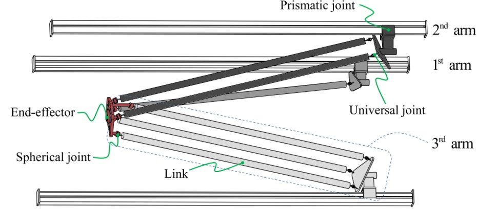
The system is a 3-DOF translational parallel manipulator. It consists of a fixed base and a moving platform connected by three kinematic chains. Each arm features a prismatic joint that performs translational motion and parallelogram links that perform general plane motion. The core objective of the modeling is to derive an accurate mathematical representation for high-precision control.
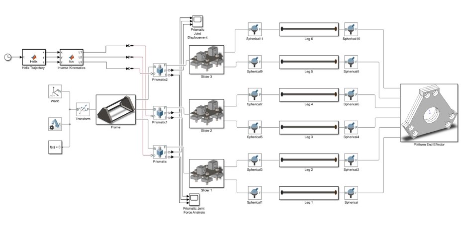
A. System Flowchart
B. Inverse Kinematics Method
Inverse kinematics is used to determine the joint variables required to reach a specific end-effector position. Starting from the loop closure equation $P + bi = ai + diui + ci + Lli$ , we simplify the constants and rearrange for $di$. For the $i$-th kinematic chain, the position of the cart is expressed as:
di = λiz ± sqrt(li² − λix² − λiy²)where $λi$ is the vector from the base to the platform minus constant geometric offsets.
C. Task Space Definition
The task space is governed by the physical dimensions of the Linear Delta Robot. Important workspace parameters include:
- Frame Height: 870 mm
- Base Side Length: 700 mm
- Prismatic Range: 70 mm to 580 mm
- Link Length: 365 mm
III. Control and Motion Planning
The control system focuses on tracking the desired helical trajectory through joint space control using an ADAMS simulation loop.
A. Spiral Trajectory for Cleaning
-
Parameters Definition:
- Frequency (ω): π/6
- Helix Radius (r): 0.01 m
- Total Time: 30 seconds
- Initial Z (z0): 0.316 m
-
Trajectory Equations:
x = r * sin(ωt)
y = r * cos(ωt)
z = z0 + v * t
B. Transition Trajectory
Motion planning for the robot is implemented through high-precision control schemes The Computed Torque Control (CTC) law is particularly effective as it linearizes the closed-loop system by compensating for nonlinear dynamics The CTC control law is defined as:
f = M(d)[d_ddot + Kp.e + Kv.e_dot] + C(d, d_dot)d_dot + G(d)IV. Trajectory Generation
A. Trajectory planning
The trajectory is analyzed through velocity and acceleration analysis to ensure smooth tracking The Jacobian matrix $Jdi$ is utilized to map the task-space velocity to the joint velocity
B. Transition Trajectory
Acceleration analysis provides the necessary input for dynamic compensation The acceleration of the $i$-th joint is given by:
di_ddot = Jdi * P_ddot + P_dot_T * Hi * P_dotwhere $Hi$ accounts for the centrifugal and Coriolis effects of the kinematic chain
V. Experimental Setup and Results
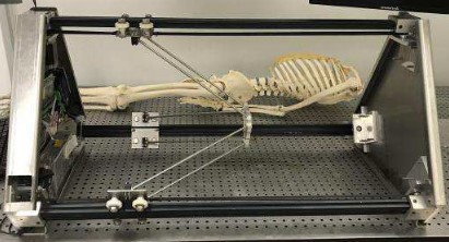
A. Initial Setup
The dynamic model was derived using the Principle of Virtual Work, incorporating a mass distribution factor (w) to simplify the inertial forces of the leg links
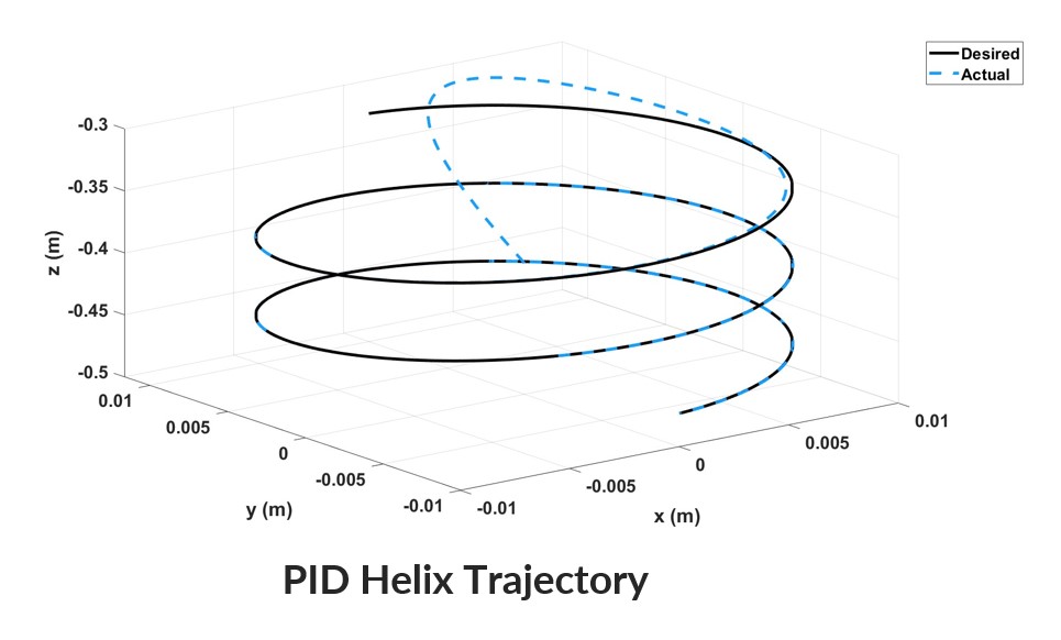
B. Simulation Execution
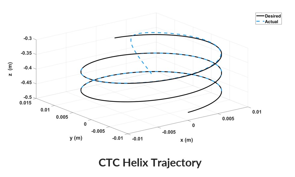
Simulations were conducted for PD, PID, and CTC controllers The results were compared to the desired helix trajectory to assess accuracy
C. Shortest Path Calculation
Root Mean Square Error (RMSE) was used as the primary metric for accuracy
e = sqrt( (1/n) * Σ(dd - d)² )D. Visualization
The tracking results show that while all controllers follow the trajectory, CTC provides the highest accuracy
VI. Conclusion
The project successfully determined the mathematical model of the Linear Delta Robot and compared PD, PID, and CTC control methods The CTC controller demonstrated superior performance with the lowest RMSE across all axes Future recommendations include using Lagrange methods for dynamics and implementing disturbance observers for experimental testing