Autonomous Quadcopter Navigation and Control
Robust Indoor Navigation and Object Detection using Stereo Camera and LiDAR
Abstract
This project involves the development of an autonomous navigation system for a quadcopter in simulated environments. The system integrates sensor fusion for localization, PID-based flight control, and dynamic path planning to enable the drone to traverse complex indoor environments. Leveraging the ROS 2 ecosystem and Gazebo simulation, the quadcopter performs autonomous navigation and collision-free movement.
1. Introduction
Autonomous aerial navigation is a critical component for applications ranging from indoor inspection to search and rescue. Unlike ground-based platforms, quadcopters must manage stability across six degrees of freedom while perceiving obstacles in 3D space. This project focuses on implementing an autonomous flight stack that coordinates flight dynamics with high-level mission planning using ROS 2.
2. System Overview
- ROS 2 Humble: The software framework for managing asynchronous sensor data and control commands.
- Gazebo Simulator: Used for physics-accurate flight simulation and sensor modeling (Lidar, IMU).
- ArduPilot: Integration with flight control firmware for low-level motor stabilization and MAVLink communication.
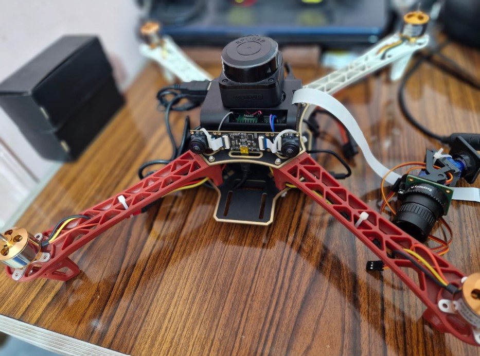
- Sensor Suite: Utilization of 2D Lidar and stereo camera for obstacle detection and IMU/Odometry for pose estimation.
3. Methodology
3.1 Environment and Flight Setup
- Design of a custom indoor environment in Gazebo featuring narrow corridors and dynamic obstacles.
- Configuration of the quadcopter URDF/SDF models with optimized weight-to-thrust ratios.
- Calibration of the simulated EKF (Extended Kalman Filter) for robust state estimation.
3.2 Stereo Camera Calibration
- The stereo camera was manually calibrated using ROS2 nodes
- A ROS2 node was developed and used in the pipeline for the image processing
3.3 Disparity Maps
- The feature matching will be used for disparity maps
- Depth maps will be computed from the disparity
- The calibrated stereo camera was utilized
3.4 Cartographer SLAM
- The LiDAR was used to generate Point Clouds for the SLAM algorithm
- Real-time SLAM was utilized and the mapping was viewed via RViz.
- The disparity map shown requires further tuning of the parameters for clearer map
3.5 Autonomous Navigation
- In progress